Home
|
About Us
|
Capabilities
|
Markets Served
|
Quality Assurance
|
Literature
|
Distributor & Rep Locator
|
What's New
|
Contact Us
Switches
Indicator Lights
Connectors
Defense/Aerospace Connectors
Contract Manufacturing
Custom Assembly
Custom Switches and Connectors
Search Catalog
By Keyword
By Item #
All Categories
Side Actuated Slide Switches
All Categories
>
Switches
>
Slide Switches
>
Standard Slide Switches
>
Side Actuated Slide Switches
>
Item # GG-372-0001
Download PDF
Download PDF
Printable Page
Email This Page
Save To Favorites
Please wait…
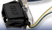
Item # GG-372-0001, GG - Series Single Pole/Double Throw (with Detent) Standard Slide Switch
larger image
Specifications
·
Available Options
·
Materials
·
Performance Standards
·
Care in Switch Installation
Specifications
Circuitry
SPDT
Switch Function
ON-ON
Electrical Ratings
0.5 A @ 125 VDC
3 A @ 125 VAC
Acuator Style & Color
Radius Knurled - Black
Actuator Height
0.515 in.
Mounting
Self Supporting
Terminal
PC - with Solder hole
Solder Shield
Vulcanized Fiber Shield 0.020" thick that fits over the switch terminals is also available
Listing Agency
(Consult drawing or factory for specific rating)
1
Listed Agencies
Compliance
.
1
Due to ongoing advancements, additional agency certifications may be available, contact us for more information.
Available Options
See Downloads on this page for available Actuator style and height options and Terminal types.
Materials
Button Material
Nylon 6/6
Housing
Cold Rolled Steel
Housing Plating
4-point PC board mount switches-electro-tin; others - zinc followed by clear chromate.
Panel: Zinc, PC Board: Electro-tin
Moving Contact
Copper Alloy
Moving Contact Plating
Silver is standard. Gold plating is an option, consult factory.
Moving Contact Spring
Beryllium Copper
Phosphor Bronze
Terminals
Copper Alloy
Terminal Plating
Silver is standard. Gold plating is an option, consult factory.
Terminal Board
NEMA Grade XP Phenolic Laminate
Performance Standards
CW switches are designed to perform to the standards listed when operated within ambient conditions detailed below:
Operating Temperature
- 104ºC maximum, -10ºC minimum.
Relative Humidity
- Switches will be operable and insulation resistance shall be greater than 100 megohms if allowed to dry for 100 hours at room temperature of 25ºC and after exposure for one hour in an atmosphere having 95% relative humidity and a temperature of 50ºC
High Voltage Breakdown
- Minimum of 1000 volts RMS 60 Hz for one minute between parts of opposite polarity.
Contact Resistance
- Less than 0.01 ohm at 20 milliamperes DC.
Life Cycling (No Load)
- Switches will be operative after 10,000 (minimum) cycles at the rate of 10 cycles per minute.
Life Cycling (Load)
- Switches will be operative after 6000 (minimum) cycles at the rate of 10 cycles per minute at rated load
Care in Switch Installation
CW switches will perform properly if they are installed and used properly. Causes for failure often encountered in the field that are the responsibility of the user are:
Removal of factory applied lubricants from switch contacts and moving parts.
Introduction of foreign material into switching mechanism...flux, solder cleaning materials, potting compounds.
Restriction of movement of switch button.
Excessive heat often introduced while soldering.
Switching loads in excess of rating.
Manufacturing Engineers are cautioned to avoid misusing switches and resultant switch failures.
DOWNLOADS
Slide Switch Schematic
(PDF, 645KB)
GG-372-0001_2D DRAWING
(PDF, 114KB)
GG-372-0001_3D MODEL
(STP, 781KB)